

In my previous post, available here, I have shown you the initial stages of designing and developing our own IoT controller. Today, while the PCB has just arrived from PCBWay, and while we wait for the rest of the components to arrive, we will continue with the software development of the device. I will also show you the beautiful PCB that I got from PCBWay!
For today’s post, we will focus on configuring ESPHome, get it to work together with Home Assistant, as well as have a look at those PCB’s!
Table of Contents
Configuring ESPHome
The YAML configuration file
Updating the prototype device OTA
Integrating it all with Home Assistant
Taking a look at the PCB’s
Conclusion of Part 2
Configuring ESPHome
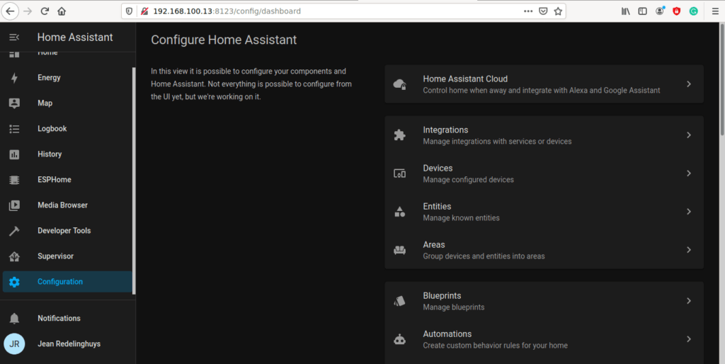
In the last post, we left off here…
Our next step will be to write the YAML configuration file…
YAML configuration
ESPHome uses the YAML language to define IO and automation. These files are then parsed, converted into C/C++ and compiled. The resulting Binary File is the uploaded OTA to the device via WiFi.
We will still be using our Virtual Machine Image of Home Assistant, running inside VirtualBox on our PC.
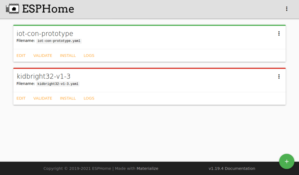
Go ahead and start that, and then open Home Assistant in your Web Browser. Then click on ESPHome.
You will see a screen similar to the one above.
While we are at this point, I believe it is a good time to clarify why we do the development in a virtual PC, and not directly on our Home Assistant instance running on a Raspberry Pi. The reason is actually very simple. Home Assistant seems to have issues with completely removing unused entities. This is not a problem, but you could potentially end up with a lot of stale entries in your production Home Assistant Server. The VM solution allows us to test everything away from the actual server, and then, when we are done, recreate the working device on the actual server. That way, there is almost no chance of damaging your existing Home Assistant Server, which you may already have spent some time on to set up just the way you want it…
Continue by clicking on the EDIT link, in the iot-con-prototype device that we created in the last tutorial.
You will see a file similar to this …
esphome:
  name: iot-con-prototype
  platform: ESP8266
  board: nodemcuv2

# Enable logging
logger:

# Enable Home Assistant API
api:

ota:
  password: "3f132fc270315361e4d2393a50c2bac5"

wifi:
  ssid: "<your ssid here>"
  password: "<your password here>"

  # Enable fallback hotspot (captive portal) in case wifi connection fails
  ap:
    ssid: "Iot-Con-Prototype"
    password: "4uSytyPTx1TO"

captive_portal:
This is the default configuration file generated by ESPHome. We will build on this file… Note that your OTA Password will be different. DO NOT CHANGE OR MODIFY IT IN ANY WAY!
When we edit YAML, indentations are extremely important, so try to follow exactly what I am doing.
Our IoT Controller uses I2C to communicate with the PCF8574 chip. Let us assume that you have set your address to 0x22h by using the dip switch on the PCB, you could of course set any other address, just make sure that you know what it is.
We now need to tell ESPHome that we have an I2C Bus and that it needs to scan this bus for devices. That way, we can see in the logs if it actually detects our device or not.
Add the following 5 lines to your file:
i2c:
  sda: GPIO4
  scl: GPIO5
  scan: true
  id: i2c_bus_a
They mean that we will have an I2C bus with SDA on GPIO4, and SCL on GPIO5.
The bus will have an ID of i2c_bus_a and the bus should be scanned
The next section will be the actual PCF8574 Io Expander
Add the following lines to the file:
pcf8574:
  - id: 'pcf8574_hub'
    address: 0x22
    pcf8575: false
We give this device the id of pcf8574_hub and specify its address as 0x22. We also NEED to specify that it is NOT the 16 port pcf8575 variant.
Now we can start configuring our outputs. for our purposes, we will have two relay outputs, as well as two status LEDs. In the actual circuit, the pcf8574 will sink the pins connected to these, as the chip can sink more current than it can safely source. Refer to the relay driver schematic for more information on that.
Go ahead, and add the following to your file.
output:
 - platform: gpio
   id: relay_1
   pin:
      pcf8574: pcf8574_hub
      number: 0
      mode: OUTPUT
      inverted: true
 - platform: gpio
   id: relay_2
   pin:
      pcf8574: pcf8574_hub
      number: 1
      mode: OUTPUT
      inverted: true
 - platform: gpio
   id: led_status_1
   pin:
      pcf8574: pcf8574_hub
      number: 2
      mode: OUTPUT
      inverted: true
 - platform: gpio
   id: led_status_2
   pin:
      pcf8574: pcf8574_hub
      number: 3
      mode: OUTPUT
      inverted: true
The syntax should be straightforward, every output will have a platform, in this case, gpio.
Then we will need a unique ID, let us say relay_1
Now, we need to specify the physical pin to use. Now here, you could also specify a native pin on the actual NodeMCU device that we are using for testing, but we will specify a pin on the pcf8574 instead.
This is done with the pin: directive
pin:
pcf8574: pcf8574_hub // This tells the parser to use the device at address 0x22 that we specified before.
number: 0 // use GPIO 0
mode: OUTPUT // this can be either INPUT or OUTPUT, for our case, it should be OUTPUT.
inverted: true // Invert the logic of the pin.
Once again, it is needed, as we are sinking current into the pin, and the circuit was designed that way…
You can however use it noninverted if you really want, it will just look a bit odd on Home Assistant, if your On state, actually meant Off
The next section will be called binary inputs and may seem a bit confusing at first. But, trust me, it is not. This is just the way that we define our physical push buttons on the device. We need those, in the event that our Home Assistant Server is offline, or when we need to physically press a button on the device.
What? Why? Are we not building an IoT Controller? Why should we press any physical buttons on it?
Well, the answer to that is quite obvious. There will definitely be times that you want to control an attached device by pressing a physical button. It does not make sense to scurry around, swiping through apps on your smartphone, while you are standing right next to the device in question. To leave out this basic functionality, would be plain silly, and in my view, bad engineering.
binary_sensor:
  -  platform: gpio
     id: push_button_1
     name: 'Relay1 Pushbutton'
     device_class: ''
     pin:
        pcf8574:  pcf8574_hub
        number: 4
        mode: INPUT
        inverted: true
     on_press:
      then:
        - switch.toggle: switch_relay1
     filters:
       -  delayed_on_off: 50ms

  -  platform: gpio
     id: push_button_2
     name: 'Relay2 Pushbutton'
     device_class: ''
     pin:
        pcf8574:  pcf8574_hub
        number: 5
        mode: INPUT
        inverted: true
     on_press:
      then:
        - switch.toggle: switch_relay2
     filters:
       -  delayed_on_off: 50ms
The syntax is almost the same as the outputs above, but we are also adding automation:
We want the relay to be toggled each time the button is pressed. This will allow us to use only one button per relay to switch it on or off.
We are also adding a filter, in this case, a bit of debouncing, of 50ms. This will prevent the chattering of the contacts on the switch from generating more than one event for each button press.
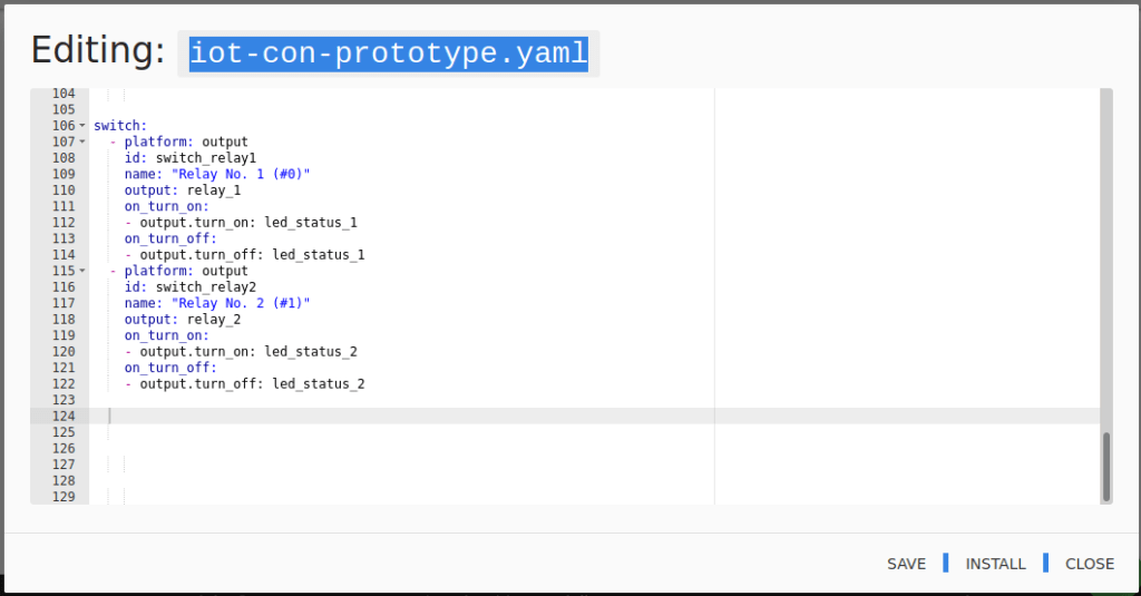
The final section of the file will be a switch: section. This will allow you to control the relays from inside Home Assistant. ( The outputs are considered an internal to ESPHome function, and will thus not be exposed to Home Assistant.
Add the following lines to the file
switch:
  - platform: output
    id: switch_relay1
    name: "Relay No. 1 (#0)"
    output: relay_1
    on_turn_on:
    - output.turn_on: led_status_1
    on_turn_off:
    - output.turn_off: led_status_1
  - platform: output
    id: switch_relay2
    name: "Relay No. 2 (#1)"
    output: relay_2
    on_turn_on:
    - output.turn_on: led_status_2
    on_turn_off:
    - output.turn_off: led_status_2
You can see that the syntax is once again very easy to understand. We also specify that the status LED for the relevant relay channel be switched on or off with the relay. This also happens when you press the physical switch.
The name element will be the Name of the Output that will be displayed in Home Assistant. You can change it to your liking here, or you can also change it inside Home Assistant itself.
The completed file should now look like this. NOTE that if you decide to copy-paste the file from here, as I would recommend, you should only copy from the i2c section to the end of the file. Do not copy the WiFi and other sections. Your own file already has your own settings.
esphome:
  name: iot-con-prototype
  platform: ESP8266
  board: nodemcuv2

# Enable logging
logger:

# Enable Home Assistant API
api:

ota:
  password: "3f132fc270315361e4d2393a50c2bac5"

wifi:
  ssid: "<your ssid here>"
  password: "<your password here>"

  # Enable fallback hotspot (captive portal) in case wifi connection fails
  ap:
    ssid: "Iot-Con-Prototype"
    password: "4uSytyPTx1TO"

captive_portal:
#DO NOT COPY ANYTHING ABOVE THIS LINE --------
i2c:
  sda: GPIO4
  scl: GPIO5
  scan: true
  id: i2c_bus_a

pcf8574:
  - id: 'pcf8574_hub'
    address: 0x22
    pcf8575: false


output:
 - platform: gpio
   id: relay_1
   pin:
      pcf8574: pcf8574_hub
      number: 0
      mode: OUTPUT
      inverted: true
 - platform: gpio
   id: relay_2
   pin:
      pcf8574: pcf8574_hub
      number: 1
      mode: OUTPUT
      inverted: true
 - platform: gpio
   id: led_status_1
   pin:
      pcf8574: pcf8574_hub
      number: 2
      mode: OUTPUT
      inverted: true
 - platform: gpio
   id: led_status_2
   pin:
      pcf8574: pcf8574_hub
      number: 3
      mode: OUTPUT
      inverted: true

binary_sensor:
  -  platform: gpio
     id: push_button_1
     name: 'Relay1 Pushbutton'
     device_class: ''
     pin:
        pcf8574:  pcf8574_hub
        number: 4
        mode: INPUT
        inverted: true
     on_press:
      then:
        - switch.toggle: switch_relay1
     filters:
       -  delayed_on_off: 50ms

  -  platform: gpio
     id: push_button_2
     name: 'Relay2 Pushbutton'
     device_class: ''
     pin:
        pcf8574:  pcf8574_hub
        number: 5
        mode: INPUT
        inverted: true
     on_press:
      #min_length: 50ms
      #max_length: 500ms
      then:
        - switch.toggle: switch_relay2
     filters:
       -  delayed_on_off: 50ms
switch:
  - platform: output
    id: switch_relay1
    name: "Relay No. 1 (#0)"
    output: relay_1
    on_turn_on:
    - output.turn_on: led_status_1
    on_turn_off:
    - output.turn_off: led_status_1
  - platform: output
    id: switch_relay2
    name: "Relay No. 2 (#1)"
    output: relay_2
    on_turn_on:
    - output.turn_on: led_status_2
    on_turn_off:
    - output.turn_off: led_status_2
Well done, That was quite easy.
Copy and paste the file into the edit screen that you have opened in ESPHome.
If everything went well. you should see an option to save or install as in the picture below.
If you can see both Save and Install, it means that your file syntax is correct. If not, go back and carefully check your indentations, as well as the spelling of the commands. It should not be a problem if you copied it from above…
Now click on save. You will get a confirmation.
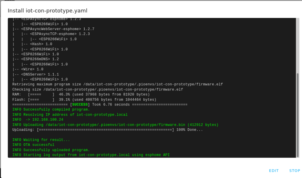
Make sure that the prototype is connected to the USB port of the computer, or to another power source. Wait a few seconds to make sure that it is connected to the network, and then click Install.
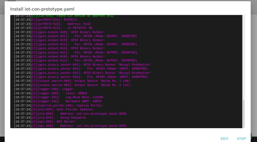
ESPHome will now parse your YAML file, generate the needed code, and compile it. After that, it will upload the new firmware to your device. Wait until you can see the device restart and connect to the network in the log window.
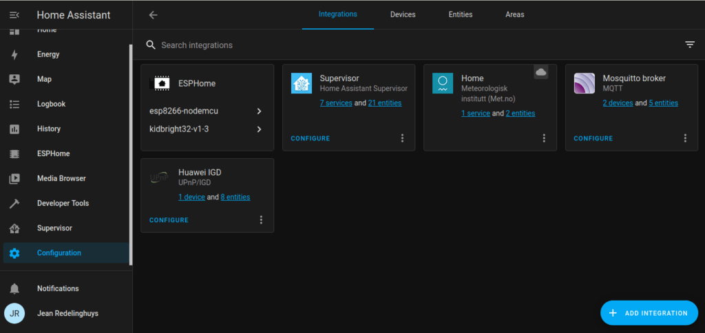
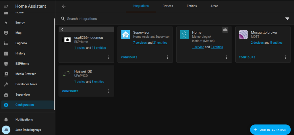
Configuring Home Assistant
We can now start to add this all to Home Assistant. It is also very likely that you will be prompted to add the device by Home Assistant itself. If this did not happen, or like with my testing image on the VM, you have a lot of old stuff floating around as well, we can do it manually …
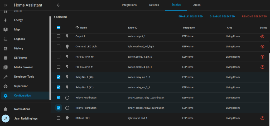
We can now select the two relays, as well as the Pushbuttons. Then click on Enable selected.
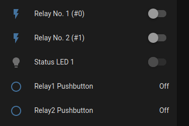
When you now go back to the Home Assistant Home screen, you will see your device with its controls, on the screen. You can now control the device from Home Assistant. You will note that the two push-buttons are also present in Home Assistant, but, they are only indicators. This means that while they will change state briefly when you press the physical switches, they can not be controlled directly from Home Assistant. They can however be used in automation, or at least I believe so. The debouncing times are however rather short, so I would recommend that you base any automation on the actual relay states instead.
A sneak preview of the PCB
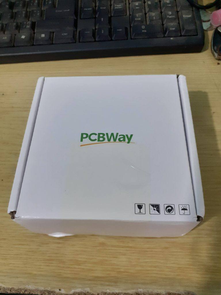
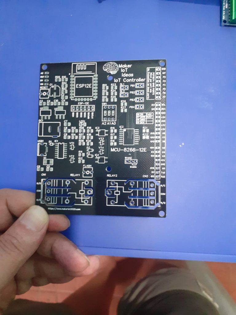
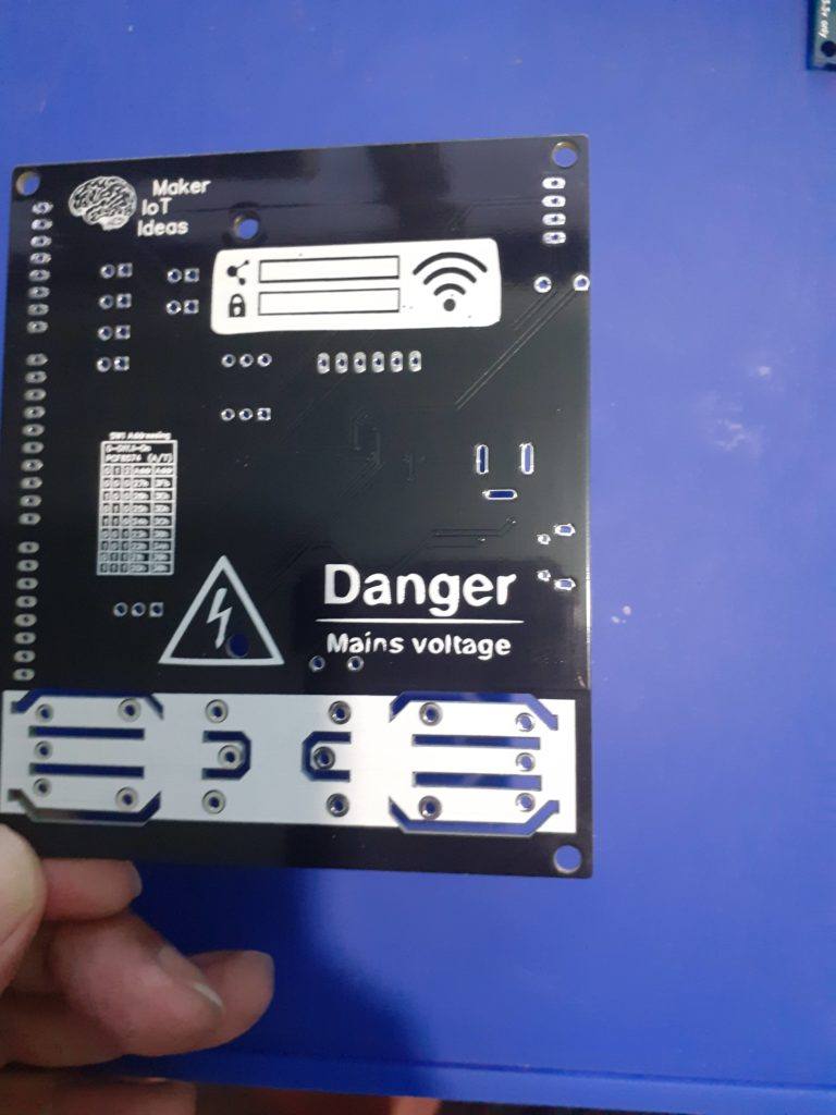
As promised above, I will now give you a quick preview of the PCB’s. They were manufactured by PCBWay

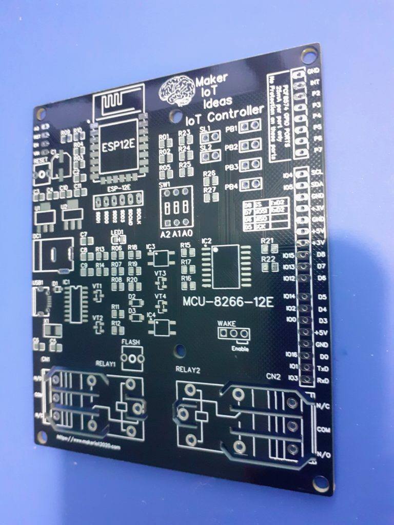
I am once again awed by the precision of these bords. They are absolutely flawless and exactly true to my design.
The irregular isolation cut-outs are exactly to speck and size, the silkscreen is crisp and not blurred. All component footprints are correct, and there seem to be no shorts or open circuits on initial testing with a multimeter.
You can get your own version of these for only $USD 5.00 excluding shipping from here I believe you will be just as impressed as I am.
So let us look at these boards…

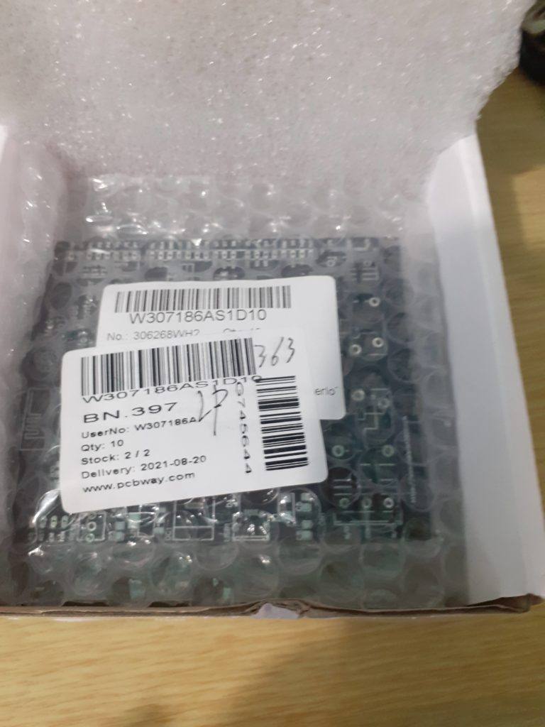
PCB’s in packaging Securely packaged in vacuum-packed bubble wrap Topside of the PCB Top Side of PCB Back of PCB, isolation cutouts clearly visible
My biggest frustration now will be to wait for the rest of the components to arrive. I already have some of them in stock, and can repurpose some others, but I think that I will rather wait for everything to arrive so that I don’t have to
assemble them in stages. I plan to assemble 2 of the 10 boards and make some of the remaining 8 available to interested people. Contact me on messenger if you are interested.
Conclusion
This concludes part 2 of this series. In part 3, we will look at the assembled PCB’s, as well as take a more detailed look at using them together with Home Assistant. I will also attempt to do the Tasmota integration, this will involve compiling my own special version of Tasmota.
I am also planning to release the assembly process as a series of pictures or maybe a video on Patreon.
If you like what I do, I want to ask you to consider becoming a Patron. With some assistance from generous people like yourself, I can create some more interesting projects.
Thank you, and Good-Bye until next time.