
Today I will introduce the H-Bridge Motor Controller. You can easily order a motor controller online or from a shop, but what about those big 18 v Battery Drill motors lying in the corner, or the big dc motor you found in an old photocopier or printer. Buying a controller for those can get tricky as well as expensive, whereas buying a few discrete components and a piece of project-board, and investing some time, while also learning something, may be much more worth the time spend, as well as cheaper.
Controlling a motor seems like a very easy thing to do, just connect power to the two leads and it turns, right? Yes but not quite. I have seen many things online, most of them ok, but some not quite so good, but let us start with the basics.
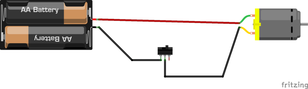
This is where most of us would, or would have started playing with motors. A power-source, like a battery, and a switch, if available. This is quite easy to do, and will result in a motor that starts to “work” immediately. It does however have quite a few problems:
- It runs at a fixed speed
- It runs in a single direction
- It definitely does not run at with a lot of power to do actual work…
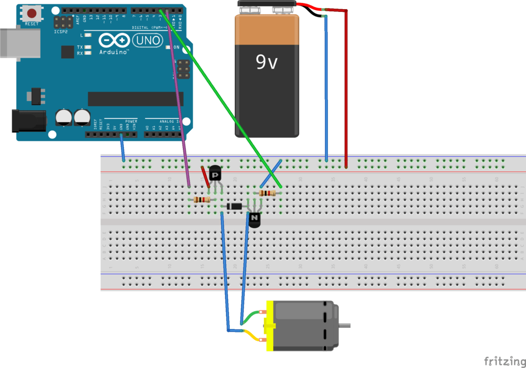
We can improve on this circuit by doing the following:
In this circuit, we can use a small voltage to switch the motor on, while using a big voltage to run the motor. This provides more speed, and ultimately more torque, but it is important to stay within the power and voltage requirements of the motor. The most important feature of this circuit is that the switch can be replaced by a micro-controller, thus you can use PWM to control the speed of the motor. You are however still limited in the fact that the motor only spins in one direction.
This circuit’s performance can be improved by adding another transistor, this time a P-N-P type, as well as a diode to protect the transistor(s) from the inductive load of the motor.
In order to use this circuit, you have to pull Pin 2 LOW and apply a PWM Signal to Pin 3.
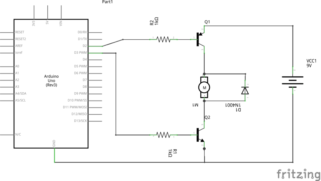
The transistors will push and pull current into and through the motor, giving more torque, and making it more effective. We are however still stuck with our original problem of not being able to reverse the direction of the motor. We will address that in the next step, by simply duplicating our circuit, and adding a few more components.
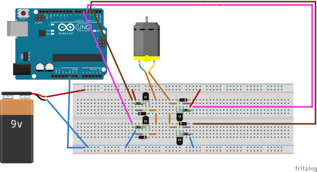
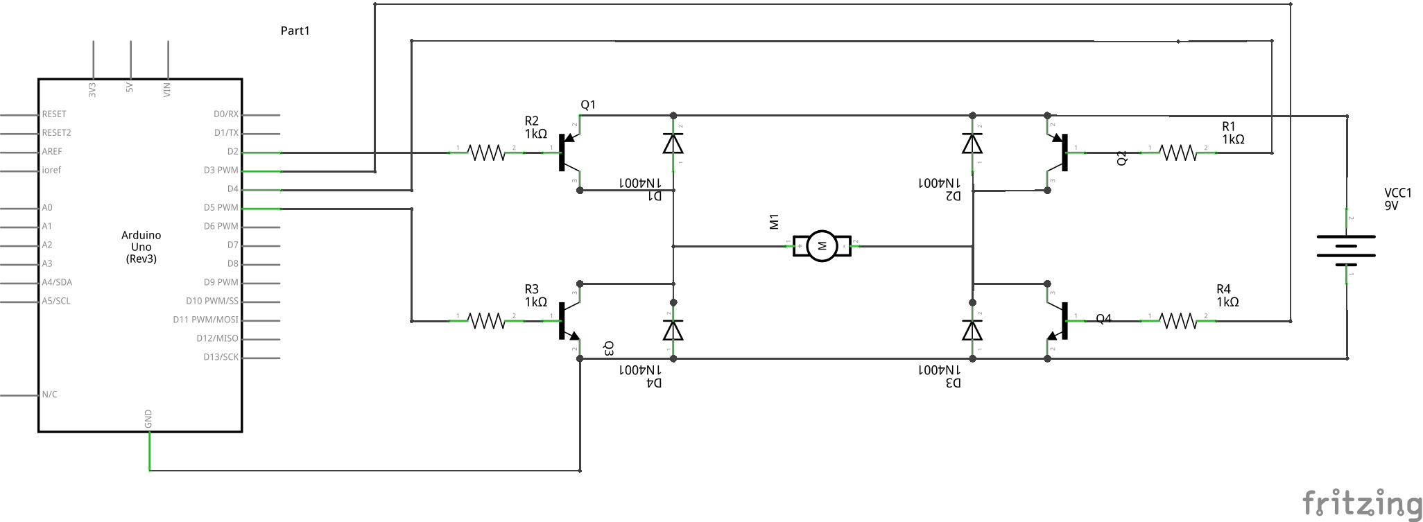
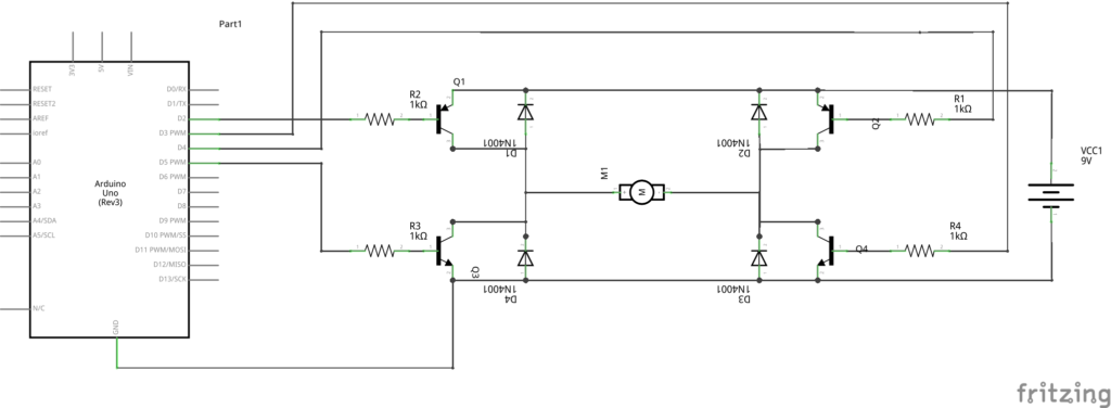
This is the completed circuit. It looks extremely complicated, but in fact it is not. Lets have a closer look…
How does this work?
First we must understand a little bit about transistors Q1 and Q2 are P-N-P Transistors, current flows from the Emitter to the Collector, Q3 and Q4 are N-P-N Transistors, current flows from the Collector to the Emitter. The second thing we need to understand is that to switch on a P-N-P transistor, the base (R1 or R2) must be pulled LOW. The N-P-N transistors, the base (R3 or R4) must be pulled HIGH.
You must also choose the right matched pairs of PNP and NPN transistors. This will depend on the size of your motor, and the current and voltage required, for small toy or hobby motors, 2N2222A as NPN and 2N2907A as PNP will give moderate performance. ( You can also use NPN 2N3904 and PNP 2N3906, but this combination gives poor performance) ZTX1049A (NPN) and ZTX968 (PNP) will give optimum performance 🙂
For bigger motors, lets say RC type (not 3-phase in-runner or out-runner) DC Motors, I have found that the TIP120,TIP121 and TIP122 as NPN and TIP125,TIP126 and TIP127 as NPN can handle currents of up to 5A and peak up to 8A ! Please use a decent heatsink, and remember that these transistors are quite big (TO-220).
Let us get back to explaining how this works.
Control pins from Arduino is as follows:
D2,D4 These enable or disable (switch on or off a specific PNP transistor (Q1 or Q2 ) by being pulled LOW (to ground).
D3 and D5 are PWM or normal digital outputs that turn on Q3 or Q4 by being pulled HIGH (to VCC)
Let us say you want to make your motor run forward (obviously this may actually be reverse, but for example’s sake)
Pull D4 HIGH , D5 LOW, and D2 LOW. Now apply a PWM signal to D3, or pull it HIGH. What happens ?
Pulling D2 LOW switches Q1, Pulling D5 High or applying PWM to it, switches on Q4. Q2 and Q3 are kept off.
This now pulls and pushes current from Q1, through the motor, and out to ground through Q4, making the motor turn in on direction, lets say forward.
To reverse this, D2 HIGH, D4 LOW, D5 LOW and D3 HIGH or Apply PWM to D3. This makes current flow from Q2, through the motor from the other side and out at Q3, effectively reversing the direction of the motor.
There are however some states that will cause the battery to short! Never use the following combinations together
D2 LOW with D5 High or in PWM
D4 LOW with D3 High or in PWM
This will cause the battery voltage to short directly to ground!
Sample code for Arduino
/*
* Example code to use with DIY H-Bridge ( One Motor )
* Another second motor will need another H-Bridge, and control pins
*
* Maker and IOT Ideas 2020 (MakerIOT2020)
*/
/* Define control pins */
const int fwd_enable=2;
const int fwd_pwm=3;
const int rev_enable=4;
const int rev_pwm=5;
void setup()
{
// Set pin Modes, while preventing accidental short of supply
digitalWrite(fwd_enable,HIGH);
digitalWrite(rev_enable,HIGH);
// force PNP transistors to stay off;
digitalWrite(fwd_pwm,LOW);
digitalWrite(rev_pwm,LOW);
// force NPN transistors to stay off;
// now set the pin mode.
pinMode(fwd_enable,OUTPUT);
pinMode(rev_enable,OUTPUT);
pinMode(fwd_pwm,OUTPUT);
pinMode(rev_pwm,OUTPUT);
}
void stop_all()
{
/* This will stop everything,
* allowing the motor to run free or coast)
*
*/
digitalWrite(fwd_pwm,LOW);
digitalWrite(rev_pwm,LOW);
digitalWrite(fwd_enable,HIGH);
digitalWrite(rev_enable,HIGH);
}
void motor_fwd()
{
/*
* Makes the motor run “forward”
* If you find that it actually reverses your motor,
* please swap the physical wiring at the motor once.
* It should now work correctly forever …
*/
digitalWrite(rev_enable,HIGH);
digitalWrite(rev_pwm,LOW);
// Make sure about the states of the other side of the
// H-Bridge, to prevent shorts
digitalWrite(fwd_enable,LOW);
digitalWrite(fwd_pwm,HIGH);
// Motor will now be on and running, at a fixed speed
}
void motor_fwd_pwm(int motor_speed)
{
digitalWrite(rev_enable,HIGH);
digitalWrite(rev_pwm,LOW);
// Make sure about the states of the other side of the
// H-Bridge, to prevent shorts
digitalWrite(fwd_enable,LOW);
analogWrite(fwd_pwm,motor_speed);
}
void motor_rev()
{
digitalWrite(fwd_enable,HIGH);
digitalWrite(fwd_pwm,LOW);
// Make sure about the states of the other side of the
// H-Bridge, to prevent shorts
digitalWrite(rev_enable,LOW);
digitalWrite(rev_pwm,HIGH);
// Motor will now be on and running, at a fixed speed
}
void motor_rev_pwm(int motor_speed)
{
digitalWrite(fwd_enable,HIGH);
digitalWrite(fwd_pwm,LOW);
// Make sure about the states of the other side of the
// H-Bridge, to prevent shorts
digitalWrite(rev_enable,LOW);
analogWrite(rev_pwm,motor_speed);
}
void motor_brake()
{
/*
* This will brake the motor, or make it slow down
*/
digitalWrite(fwd_enable,HIGH);
digitalWrite(rev_enable,HIGH);
digitalWrite(fwd_pwm,HIGH);
digitalWrite(rev_pwm,HIGH);
}
void motor_brake_intervals(int brakes = 2)
{
// this will brake the motor x times, default of 2
// delay used here for ease of explanation, feel free to change
// this to millis
for (int i = 0; i < brakes; i++)
{
motor_brake;
delayMicroseconds(10);
stop_all();
delayMicroseconds(10);
}
// and allow motor to run free
stop_all();
}
void loop() {
// Sample use
// Start with a stopped motor
stop_all();
// go forwards
motor_fwd();
delay(2000);
// brake and stop
motor_brake_intervals(5);
// reverse direction
motor_rev();
delay(2000);
// brake and stop
motor_brake_intervals(5);
// PWM slow to fast
for (int i = 155; i < 255; i+=10)
{
motor_fwd_pwm(i);
delay(100);
}
// brake and stop
motor_brake_intervals(5);
delay(500);
// Reverse fast to slow
for (int i = 255; i > 155 ; i-=10)
{
motor_rev_pwm(i);
}
// brake and stop
motor_brake_intervals(5);
delay(500);
stop_all;
}
This concludes this part of the tutorial. Next time, I will show you how to build your own, as well as give you access to a free PCB design that you can download and use to make your own dual channel H-Bridge PCB.